Skip to content
Back to experience

Role

Industry 4.0 · AMOA · Product Owner

Saint-Gobain Glass France · Chantereine plant · Thourotte, Oise

For twenty-five weeks I worked on the COMPO shop floor at the Chantereine plant, within the digital transformation and Industry 4.0 scope, under the supervision of the 4.0 projects coordinator. My assignment combined industrial process analysis, AMOA, Product Ownership, functional modelling, development on an Ignition SCADA platform, data structuring, user management, validation under real plant conditions, technical documentation, training and change management.

The project started from an operational need, not from a closed set of specifications, and the same work ended up being defended from two different academic perspectives: at Arts et Métiers from the process diagnosis and transformation, and at UNET from the system's engineering, its architecture and the results obtained. That dual reading sums up the assignment fairly well: first understand the physical process, then build a digital representation capable of supporting it.

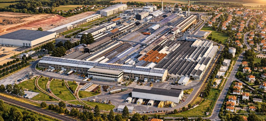
Chantereine plant, Thourotte
Saint-Gobain Glass France · Chantereine plant

Feb 2025 — Jul 2025

Ignition SCADASQLOT/ITAMOA

  • Digitalisation
  • Operations
  • People
25WeeksFebruary to July 2025, full-time at the plant
2Theses defendedSFE at ENSAM Cluny · TAP at UNET
8.5 / 9Supervisor's evaluationLine manager · «excellent» category
9 / 9TAP gradeUNET panel, December 2025

My responsibility

Process diagnosis, requirements, functional architecture, SCADA development, data model, user profiles, on-site validation, training and documentation.

Result

System deployed, 26 operating procedures, 2 technical manuals and handover to users.

The challenge

  • The logistics of the COMPO shop floor rested on three independent Excel workbooks, updated by hand once a day
  • The information existed but was fragmented: there was no single digital sequence of the material's path
  • Preparing information for internal and external audits meant consolidating sources and checking them manually
  • I did not receive a specification: actors, operations, exceptions and business rules were still to be defined

How I approached it

  1. Diagnosis on the plant floorI spent the first five weeks analysing historical documents, observing the shop floor and interviewing operators, managers and IT.
  2. Formalising the flowI defined which data was created at each stage, who generated it, who had to validate it and which event allowed moving to the next stage.
  3. Data model and profilesI structured the database into eight domains and the interface into six user profiles before declaring any window finished.
  4. Iterative development with FDDI progressed by features validated with users on the running shop floor, not in an isolated environment.
  5. Documentation and handoverI prepared 26 illustrated procedures and two technical manuals, and trained the department staff.

System view

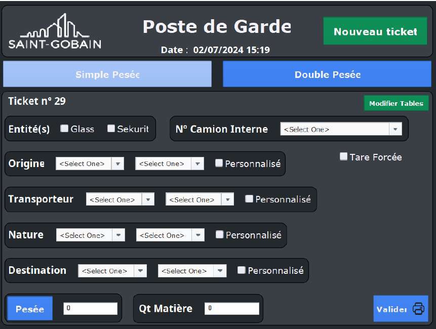
Guard post window in Ignition SCADA: truck weighing log
The guard post, the first stage of the journey. Single or double weighing, entity, carrier, material type and destination. The weight isn't typed in: it's read by the scale's PLC.Image edited for project confidentiality: operational data has been deliberately blurred or removed.

Work blocks

Requirements from the shop floor

I built the functional definition from actual operation: each expressed need became a verifiable function, with the origin, owner and use of each data item.

From physical flow to states

I turned the material's path (arrival, registration, weighing, inspection, silo, production, dispatch) into states with defined transitions, instead of isolated forms.

Data model in eight domains

I designed the database for two purposes: the operational one, knowing what is happening right now, and the historical one, reconstructing the path afterwards for traceability and audit.

Development in Ignition SCADA

I developed the windows filtered by six profiles, with alarm logic for the exceptions: incomplete information, pending results, validations that depend on another profile.

OT/IT consistency

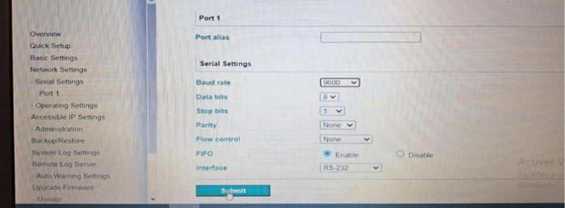
I kept interface, logic, data and physical operation aligned; the scale weight is read by the PLC through a serial-to-Ethernet converter, never typed in.

Product Owner and committees

I owned the functional scope, decided what not to develop and prepared the steering committees, separating technical detail from the detail useful for deciding.

01

The assignment

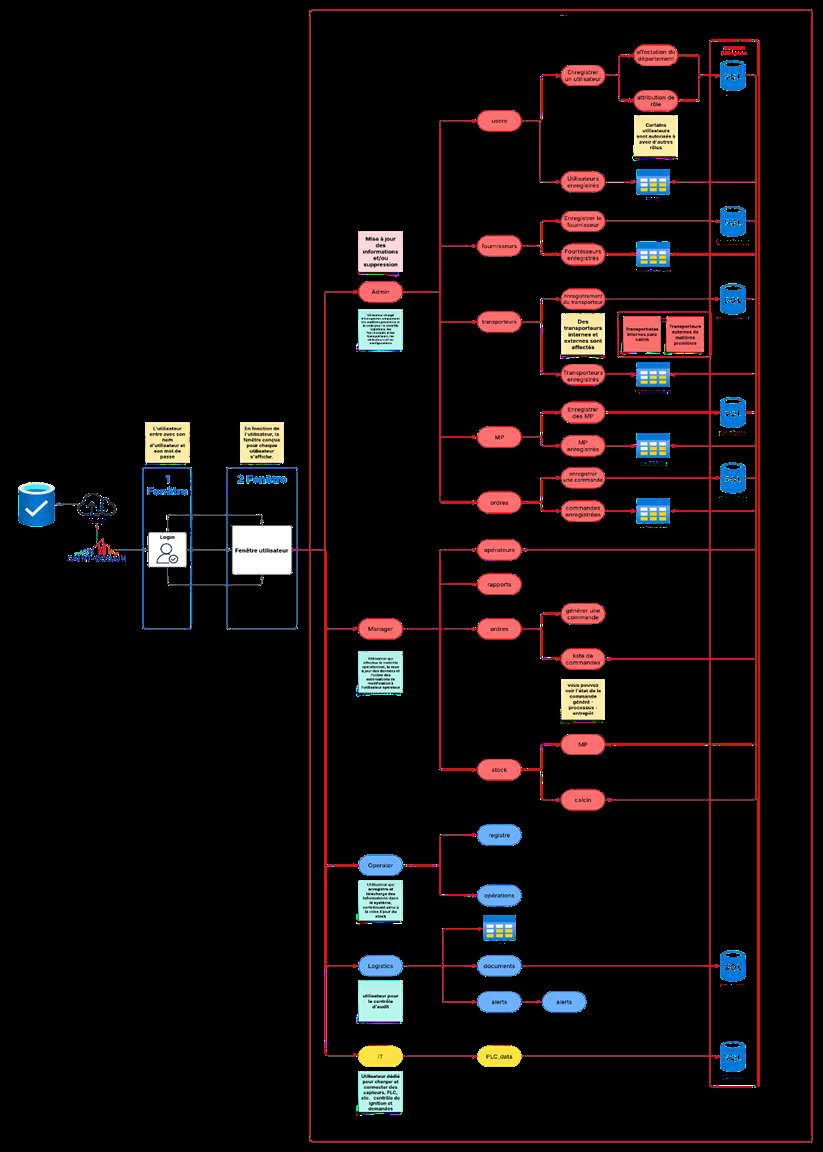
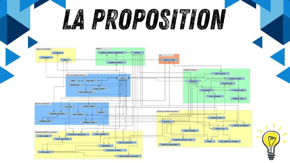
Diagram of the information flow between users proposed for the design in Ignition
The information-flow diagram between users that I presented as a design proposal. This is where the application's functional structure came from.Image edited for project confidentiality: operational data has been deliberately blurred or removed.

I joined as an assistant to project management, AMOA within Saint-Gobain's organisation, on the team responsible for the plant's digital transformation, reporting to the 4.0 projects coordinator. The mission was to develop a management tool for one of the flat-glass manufacturing and processing shop floors, with a scope covering requirements gathering, functional formalisation, analysis and modelling, development of a reporting tool, training, user support, feedback collection and successive iterations. The initial wording might suggest a mainly IT project, but in practice the work started well before the code: I did not receive a specification describing in advance every actor, every operation, every exception and every business rule, and a central part of my responsibility was precisely to build that definition from how the shop floor actually worked.

To do this I had to observe the process directly at the plant, review the existing documentation, talk to operators, production managers and IT staff, identify the points where information was generated and understand which decisions depended on it. My work sat between two languages: on one side that of production — replenishments, trucks, weighing, raw materials, cullet, checks, silos, movements, validations, production, shipments and incidents; on the other that of the system — entities, states, functional rules, user profiles, permissions, validations, events, interfaces, data persistence and traceability. The difficulty was not translating words from one domain to another, but getting both to describe exactly the same process: every need expressed from the shop floor had to become a verifiable function, every screen had to match a specific stage, every piece of data had to have an origin, an owner and a use, and every transition had to correspond to something that really happened in the operation. That formalisation work was the foundation of the project.
02

One semester, two theses, two domains

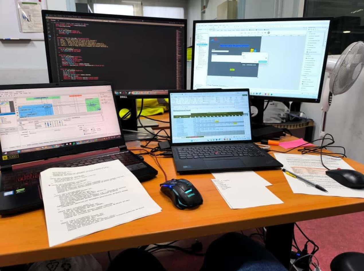
Workstation at the plant with the data model, the code and the logging window
The workstation during development. On the left the data model, in the background the code, on the right the materials-logging window in Ignition. On the desk, the draft procedures.

The same industrial project ended up becoming two different academic works, because each institution assessed a different dimension of the experience. For Arts et Métiers I submitted the SFE, «Optimisation des Processus Logistiques et Industriels par Digitalisation SCADA»: 69 pages focused mainly on the diagnosis, the transformation of the process and the transfer to users, with the industrial context, the state of the art, the methodology, the results obtained and twenty-three procedure appendices, supervised by a professor from the school and by my company mentor. For UNET I submitted the TAP, «Optimización de procesos industriales y logísticos mediante transformación digital, automatización inteligente e integración de sistemas SCADA», where the focus shifted toward the engineering of the system, its architecture, how it worked and the changes that could be demonstrated in measurable terms.

They were not two translated versions of the same document. I had to re-analyse my own work from two different frameworks: at Arts et Métiers I had to explain how I had diagnosed an industrial process, how I had structured its transformation and how I had prepared the handover of the solution to users; at UNET I had to go deeper into how the system was built, how its components related to each other and what the results obtained allowed me to demonstrate. Working this way forced me to separate three levels that in an industrial project are usually permanently intertwined: the process describes how the physical operation works, the system describes how that operation is represented, controlled and documented digitally, and performance lets you assess whether the transformation produced an observable result. Learning to move between these three levels was one of the most useful parts of the experience, because it is exactly the shift in perspective that later appears between production, IT, project management and steering committees.

03

The industrial environment

Chantereine, in Thourotte, is one of Saint-Gobain Glass's three industrial plants in France. My project was carried out mainly at COMPO, the shop floor responsible for receiving, checking and dosing the raw materials and cullet later used in float glass manufacturing, and understanding that place within the process was necessary before designing any tool.

COMPO sits upstream of the furnace and its function is not just to store materials: it is part of preparing the composition that feeds the melting process, and it therefore takes part in a continuous industrial chain in which supply regularity, raw-material quality, material identification and traceability have direct operational consequences.

Composition as a process input

In float glass manufacturing, the process begins with batch preparation, that is, the dosed mix of raw materials that will later be melted. In general, this type of composition can include silica sand, sodium carbonate, limestone, dolomite, other mineral correctors and cullet, depending on the formulation required for the product. From a process standpoint, it is not enough to know the total available volume of each raw material: dosing must stay within the set formulation, and the mix must reach the melting process with a sufficient level of homogeneity. Differences in particle size, density and material behaviour during transport, weighing and mixing require controlling preparation with a logic different from that of a conventional warehouse. The composition is a process input.

Cullet also has a particular role. Since it is glass that has already been melted before, reincorporating it allows part of the virgin raw materials to be replaced and reduces the energy needed to obtain a vitreous mass again, which means its management carries a quality, traceability, production and resource-efficiency dimension all at once.

A continuous chain

After preparation, the composition feeds the melting furnace. In a float process, the glass is brought to temperatures of around 1,500 °C before moving on to the tin bath, where the molten mass spreads out forming a continuous ribbon, and it then goes through controlled annealing and the inspection, cutting, storage and shipping stages. The key characteristic for my project was the continuity of that chain: a float line does not run on the conventional logic of starting up at the beginning of a shift and stopping at the end of the day; it is designed to work continuously over extended industrial campaigns.

That changes the way you design the tools connected to its operation. When I arrived at COMPO I was not digitalising an isolated administrative activity, but working on the information management of a shop floor located at the start of a continuous production chain. The role's overall scope covered the factory's different shop floors, and my main responsibility was focused on COMPO. I arrived on 3 February 2025 and finished the assignment on 31 July.

04

My responsibility as Product Owner

In addition to the AMOA responsibilities, I took on the role of Product Owner for the solution. The job offer explicitly set out that responsibility alongside development, planning and setting up regular reporting.

For me, Product Ownership meant taking responsibility for the functional scope: I had to determine what the tool needed to solve, structure its features, set priorities, coordinate requirements coming from different stakeholders, and keep a view broad enough to stop the application from becoming a pile of independent screens.

Deciding what not to develop

As a user starts to see a solution working, new ideas, needs and requests appear. Some address real problems, others are variants of something that already exists; some affect only one profile and others change the entire flow.

Before adding a feature, I had to understand what operational problem it solved, which user needed it, what information it used and what consequences it had for the later stages.

Stakeholders and levels of communication

My clients were internal: the managers of the factory's shop floors. In day-to-day work I mainly collaborated with technical experts, operators, production managers and the IT department, and certain topics also required exchanges with the group's central experts and with offshore developers.

That environment forced me to constantly adjust the level of communication. An operator might need to discuss the exact sequence of actions within an operation; with IT it was necessary to talk about functional behaviour, data access or user management; with a project manager the conversation shifted toward planning, dependencies, risks, progress status and pending decisions. The system was the same. The information needed to work on it was not.

Inheriting existing work

A previous intern had left a preliminary design for the weighing window. Before modifying it, I had to reconstruct its logic, understand what need it was trying to solve, identify which elements could be kept, and determine which parts no longer matched the requirements I was gathering.

It was an especially instructive situation because it resembled a real industrial project much more than an academic development from scratch. In a professional environment, systems have history: there are past decisions, constraints, legacy elements and features that no one wants to break. Before changing part of a system, you need to understand why it is there.

05

From diagnosis to development

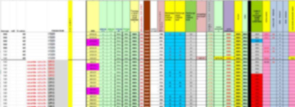
One of the Excel workbooks that supported the shop floor's logistics before the project
One of the three Excel workbooks that supported the shop floor's logistics. Updated by hand once a day; each colour was a convention only the person maintaining it knew.Image edited for project confidentiality: operational data has been deliberately blurred or removed.

The first five weeks were mainly about diagnosis. I analysed historical documents, directly observed operations on the shop floor, and conducted semi-structured interviews with operators, supervisors and members of the IT department. My goal was to reconstruct the real process: I wasn't interested only in how it should work according to a procedure, but in how it was actually carried out, what exceptions appeared, what information users consulted, and what decisions they made when the situation didn't follow the standard path. What I found was logistics management supported by three independent Excel workbooks, updated manually once a day.

The problem wasn't Excel as a technology. The problem was the fragmentation of information: each file held part of the state of the process, and getting a cross-cutting view meant consolidating different sources and manually checking that they were up to date. This affected traceability in particular, because the information existed but wasn't structured around a single digital sequence that could coherently represent the material's full journey, and it complicated preparing information for internal and external audits. From that diagnosis I began to formalise the flow: what data was created at each stage, who generated it, who could modify it, who had to validate it, what information had to be kept afterwards, what event allowed moving to the next stage, what happened when information was missing, what profile could continue the flow, and what each user needed to see in order to work without adding steps that added nothing to their operation. That analysis ended up becoming the functional foundation of the application.

From a physical flow to a digital model

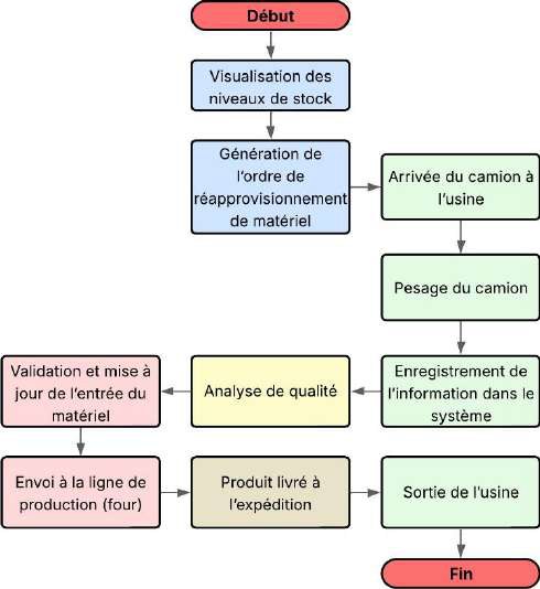
Diagram of the initial manual process in the COMPO department
The manual process as I reconstructed it during the diagnosis, from stock visualisation to the plant exit. This diagram was the starting point for the functional model.Image edited for project confidentiality: operational data has been deliberately blurred or removed.

One of the most important parts was turning the material's physical journey into states a system could understand. On the shop floor, a material arrives, is logged, weighed, checked, stored, moved to another location, and then continues to another stage; digitalising this wasn't just a matter of creating a form for each operation, because the application had to know what state the process was in, what information had already been recorded, what actions were still authorised, and which profile could carry them out.

Every transition needed its own logic. A data-entry screen couldn't be considered finished just because it stored data: I had to define what happened after saving it, what new state was generated, which user should see the operation, which fields could still be edited, which actions became locked, what relationship existed with the next stage, and what information had to be kept as evidence of the journey completed. That logic let the system stay close to the physical process instead of becoming a collection of digital forms.

The AMOA dimension

The AMOA role was especially important because my position sat between the industrial need and the IT solution. I wasn't only a user of the system, nor only a developer: I had to understand a business need, formalise it, check its consistency, translate it into functional requirements, and later verify that the solution actually met that need.

This also meant questioning some requests. A user may ask for a specific feature because they know the problem from daily experience, but the proposed solution isn't always the only one, or necessarily the best one, and before developing anything I had to separate the need from the imagined solution: what problem are we trying to solve, who runs into it, when does it appear, what information is missing, what decision can't be made, and what operation should be simplified. Answering these questions avoided adding features without first understanding their role within the process.

Iterative development with FDD

Development was organised over the 25 weeks using an agile FDD methodology, Feature Driven Development, moving forward feature by feature so each could be reviewed and validated progressively with users. This mattered especially because a written specification doesn't fully reproduce the reality of a plant: a screen can look perfectly logical in a meeting and immediately show problems when an operator tries to use it during a real operation. That's why validation wasn't confined to an isolated environment, and the tool was tested against the shop floor in operation.

Each iteration allowed comparing expected behaviour with actual use. In some cases the fix was technical; in others, the issue was one of sequence, terminology, visibility or ergonomics: a field placed in an unnatural order, information too far removed from the main action, a state that doesn't change when the user expects it to, a function that forces information to be entered twice, or a label using system language instead of the term used on the shop floor. In an industrial environment, these details determine whether a tool supports the process or gets in its way.

World Class Manufacturing as a framework

The project also had to fit into the way Saint-Gobain structures its continuous improvement. The plant works with World Class Manufacturing, with its methods for analysis, loss reduction, standardisation and performance tracking.

For me, this meant an important design constraint: the tool couldn't create a management logic running parallel to the one used by the plant, but had to fit into an organisation that already had rules, responsibilities, indicators, procedures and decision mechanisms. A solution can be technically correct and still be inadequate if it forces people to work outside the existing management system, so I tried to make the digitalisation support the industrial process rather than compete with it.

06

The solution implemented

Guard post window in Ignition SCADA: truck weighing log
The guard post, the first stage of the journey. Single or double weighing, entity, carrier, material type and destination. The weight isn't typed in: it's read by the scale's PLC.Image edited for project confidentiality: operational data has been deliberately blurred or removed.

The solution digitalised the material's journey on an Ignition SCADA platform, with a scope covering the replenishment order, truck entry, weighing, cullet quality analysis, silo storage, dispatch to production and shipping.

The SCADA platform suited this context because it brought together, in a single environment, visualisation, application logic, data interaction, authentication and access control. My goal wasn't to build an administrative application separate from the plant: the tool had to be part of the shop floor's operating environment.

A different interface depending on the user

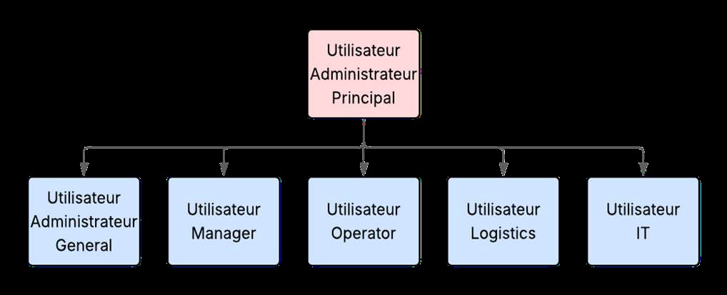
The system's six user profiles and their hierarchy
The six profiles. Each one receives only the windows and actions matching its responsibility within the process.Image edited for project confidentiality: operational data has been deliberately blurred or removed.

Windows were filtered according to the user's role, which answered a clear functional need: an operator doesn't need the same actions as a supervisor, a profile in charge of one specific stage has no reason to receive controls belonging to another responsibility, and certain actions shouldn't be available to every user.

Profile management let the interface adapt to the work each person had to do, which reduced irrelevant information and helped keep a clear separation between viewing, operating, validating and administering. In total, the system had six profiles. So I didn't design a single generic screen for the whole shop floor: the application had to show each user the part of the process they were actually responsible for.

Structuring the information

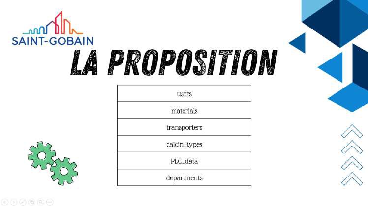
The functional domains proposed for the database
The initial proposal of domains: users, materials, carriers, calculations, PLC data and departments.Image edited for project confidentiality: operational data has been deliberately blurred or removed.
Final database design for the COMPO department
The final design, with the relationships between entities resolved and documented table by table.Image edited for project confidentiality: operational data has been deliberately blurred or removed.

Behind the windows lay a bigger problem: how to represent the process data. The system was organised around eight database domains, and that decision was necessary because digitalising a process isn't about moving Excel columns into a bigger table. Relationships between the entities involved in the flow had to be preserved: an operation could depend on a material, a vehicle, a measurement, a validation, a silo, a state or a previous stage, and each element had to be able to relate to the rest without losing its identity or its history.

The database had to serve two purposes at once. The first was operational: knowing what was happening at that moment. The second was historical: being able to reconstruct afterwards what had happened. This second dimension mattered especially for traceability and auditing, because an application that correctly shows the present but doesn't allow the past to be reconstructed has limited value in an industrial process.

From files to states

One of the most important conceptual shifts was moving from a file-centred organisation to a process-centred one. In the three Excel workbooks, each document held part of the information; in the digital solution, the different operations could belong to the same logical journey: truck arrival, logging, weighing, checking, validation, storage, dispatch to production and shipping. Each stage stopped being an isolated document and became a state within a sequence.

For me, that difference sums up the gap between computerising and digitalising well. Computerising can mean reproducing on a screen exactly what used to be written on a sheet; digitalising requires asking how information flows, what event changes the state of the process, and what each actor needs to know in order to continue.

Alarms and exceptions

The system also included alarm logic, which meant considering something that often comes up late in development: the standard flow represents only part of the real process. The ideal sequence can look simple, the material arrives, is logged, weighed, checked, stored and moves on to production or shipping, but real operation includes exceptions: incomplete information, pending results, validations that depend on another profile, operations that can't continue, data that needs correcting, or situations that must stay visible before another user makes a decision.

Designing these deviations was as important as designing the normal path. When everything goes right, almost any interface looks sufficient; the quality of an industrial tool becomes far more visible when something doesn't happen as expected.

OT/IT architecture

Serial port configuration of the serial-to-Ethernet converter
The configuration of the serial-to-Ethernet converter that takes the scale's signal off the field network. It's the exact point where the OT world becomes data that IT can read.Image edited for project confidentiality: operational data has been deliberately blurred or removed.

The project also let me work on the relationship between the operational environment and the IT environment. The application sat within an OT/IT chain where the physical operation, the SCADA interface, the application logic and the data persistence had to stay consistent, which requires thinking of the system in layers: the interface represents an operation, the logic decides which actions are allowed, the data holds the state and the history, and the user interprets that information and acts on the process.

If one of these layers doesn't match the others, inconsistencies appear. A screen can show a state the database doesn't correctly reflect; a rule can allow an action the procedure doesn't authorise; a profile can receive a function that isn't part of its responsibility; an operation can run correctly but leave no proper traceability. That's why the work couldn't be reduced to the visual design of windows: consistency had to be kept from the operation through to the stored information.

Documentation and handover

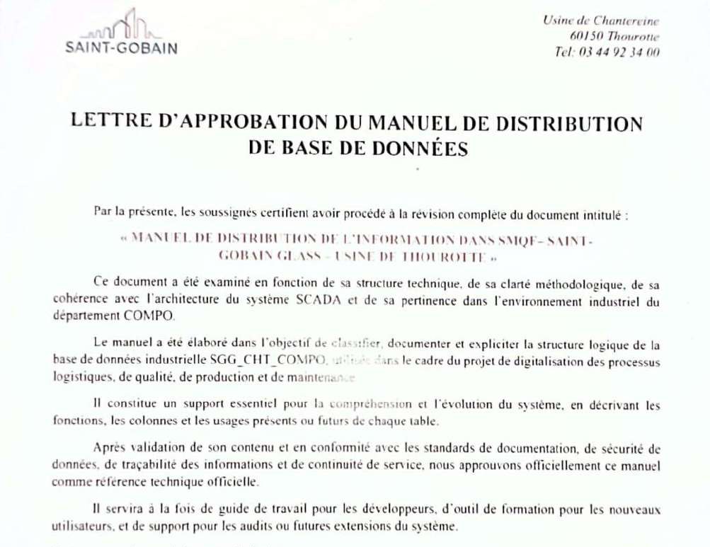
Approval letter for the database distribution manual
One of the two approval letters. The manual was formally reviewed and validated by the line manager and by the WCM 4.0 lead before becoming the department's official technical reference.Image edited for project confidentiality: operational data has been deliberately blurred or removed.
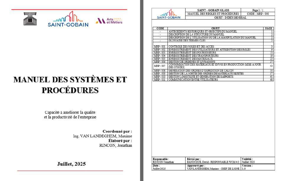
Cover of the systems and procedures manual, and the procedures index
The systems and procedures manual, and its index. Twenty-six illustrated procedures, one per operation.Image edited for project confidentiality: operational data has been deliberately blurred or removed.

Delivery didn't end with the last feature. I prepared 26 illustrated procedures, trained the department's staff, and produced two technical manuals that were reviewed, approved and signed by the line manager and by the plant's WCM/4.0 lead. I consider this part as important as the development itself, because an industrial application can't permanently depend on the person who built it: once my assignment ended, users had to be able to carry out their operations without needing me, the technical team had to have enough information to understand the tool, and the organisation had to keep formal procedures explaining how to use it.

That's why documentation wasn't a deliverable tacked on at the end. It was part of the solution. The code defines the system's behaviour, the procedure describes how the user should operate it, the manual makes its structure understandable, and the training transfers the knowledge needed for the system to keep running. I needed all four.

07

Follow-up and steering committees

Part of my responsibility was preparing for and taking part in follow-up meetings and steering committees, and this work changed quite a bit how I present technical decisions. During development I can spend time studying a data structure, a state logic, an interface behaviour or a dependency; in a committee the conversation shifts and focuses on where we stand, what's done, what's missing, what's blocking progress, what decision we need, what risk exists, what impact changing the scope would have, and when a feature can be validated.

That forced me to tell technical detail apart from the detail useful for making decisions. It doesn't mean removing engineering from the conversation, but knowing which part of the engineering each audience needs: if I had to present an architecture decision, I had to be able to explain what problem it solved, what dependency it introduced, what would happen if it failed, and what the consequences of changing it would be.

Documenting the reasoning

I also learned to better document the reasoning behind a decision. Different people join an industrial project at different times, and a decision that seems obvious today may need explaining months later to someone who wasn't there when it was made. Being able to reconstruct the why is part of the system's maintainability.

The committees also taught me to switch scale. I can go into the detail of a functional rule and, a few minutes later, step back to an overall view to explain how that rule affects planning or operations. That ability to move from architecture to process, and from process to decision, later became an important part of the way I work.

08

How I was evaluated

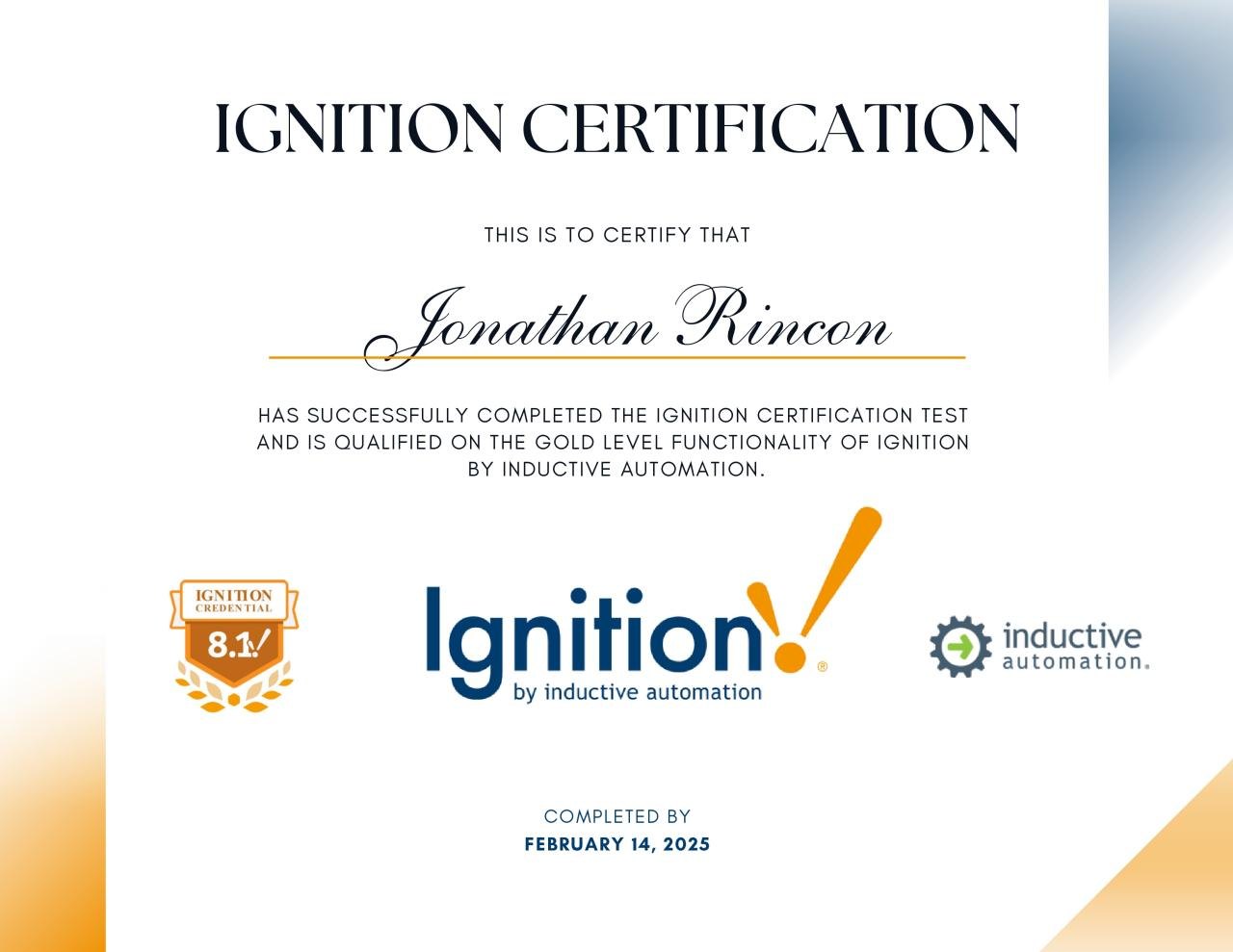
Inductive Automation Ignition SCADA Gold-level certification
The Inductive Automation Gold certification, earned on 14 February 2025: eleven days after starting the assignment. Getting certified on the platform before building anything on it was part of the assignment.

The line manager who was my external supervisor rated my performance 8.5 out of 9, in the «excellent» category, with 9 out of 9 for adapting to company standards and 9 out of 9 for technical ability. Later, the UNET panel evaluated the TAP at 9 out of 9 in December 2025.

The lowest score was for oral and written communication. It's an evaluation I understand within the context in which the experience began.

Building the language while building the system

When I arrived in France I was still developing my professional level of French, and a significant part of this assignment happened at the same time as I was building that language in an industrial setting. It wasn't just about holding everyday conversations: I had to interview users, understand technical vocabulary, take part in meetings, interpret procedures, prepare documentation, explain features, train staff, present progress and, finally, defend the project. In the SFE acknowledgements I specifically thanked the COMPO staff and the IT department for their patience with my level of French and for helping me integrate into the team.

That's why I find this part of the evaluation especially useful: it also measures the distance between the point I arrived at and the level of autonomy I reached during the assignment. I arrived working mainly from Spanish, and today I work daily in French and get by in five languages within Saint-Gobain. More than a linguistic anecdote, to me it represents the ability to join a new technical environment, learn its language, and end up working within it independently.

09

What changed the way I work

This experience mainly changed how I understand industrial digitalisation. Before, I would look at a tool mostly through its architecture and features; after working at Chantereine I began to see it as a socio-technical system, in which process, people, data, interfaces, rules, responsibilities, documentation and organisation are all part of the same solution.

If one of these elements is designed while ignoring the others, problems appear. An application can have a correct interface and a poor data model; it can have a solid architecture and not match the real flow; it can record all the necessary information and demand too much effort from the user; it can work technically and lack enough documentation to survive a team change; it can even correctly automate a process that first needed to be questioned. That's why I now try to start projects by understanding the whole system first.

Adoption isn't designed from a presentation

It also changed how I read resistance to change. I don't start from the idea that a user rejects a tool because they don't want to change: they may reject it because it adds steps, because it forces a piece of data to be entered twice, because it uses terminology nobody uses on the shop floor, because a frequent exception wasn't accounted for, because information appears too late, because they don't yet trust the state the screen shows, or because another tool rolled out earlier promised to simplify their work and ended up complicating it.

That's why I consider direct observation and validation with users part of engineering. Trust in an industrial tool is built when its behaviour repeatedly matches the reality the user knows. It isn't gained because a presentation explains the project well: it's gained when the tool responds correctly during real work.

Documenting is engineering too

Another important conclusion was to stop treating documentation as an activity that comes after development. An approved procedure sets out how an operation should be carried out, a technical manual preserves knowledge about the system, and training makes it possible to transfer that knowledge. Code on its own guarantees none of that.

If a tool disappears along with the person who developed it, the problem isn't only about documentation: there's also an organisational design problem. That's why I try to make sure the projects I build can be understood, used and maintained by people who didn't take part in creating them.

Process and engineering

The dual academic defence ended up reinforcing this way of thinking. At Arts et Métiers I had to explain how I diagnosed and transformed a process; at UNET I had to explain how the system was built and what its results made it possible to demonstrate. Both perspectives were necessary.

Today I try to keep that separation in my projects: first understand what happens physically, then model the process, then turn that model into data, states, rules, permissions and interfaces, go back to the field and check whether the digital representation still matches reality, document the decisions, and finally be able to explain the same system at the level of detail suited to an operator, an industrial manager, an IT team, a steering committee or a technical panel. That's what my work at Chantereine ended up being: not just developing a SCADA application, but understanding an industrial process, formalising it, turning it into a digital system, and preparing that system to keep running after I left.

Results and impact

Result

System deployed on the shop floor

The material's path, from replenishment to dispatch, became a single digital sequence on Ignition instead of three Excel workbooks.

26 procedures and 2 manuals

The manuals were reviewed, approved and signed by the line manager and the WCM/4.0 lead; users ran their operations without needing me.

Assessment 8.5 / 9 and TAP 9 / 9

The line manager rated the performance as “excellent”, with 9 / 9 in technical aptitude; the UNET jury graded the TAP 9 / 9 in December 2025.

Two theses defended

The SFE before Arts et Métiers, 69 pages and twenty-three procedure appendices, and the TAP before UNET, focused on the system's engineering.

Stack

Ignition SCADASQLOT/ITWCMProcess digitalisation

Skills used in the role

Tools

IgnitionSiemensOPC UAModbusMySQLSQLPythonPower BI

Domain

SCADAHMI programmingPLC programmingIndustrial automationIIoTMESInstrumentation and electricity

Frameworks and methods

WCMLean manufacturingISO 9001Industry 4.0Smart manufacturingIndustrial digitalisationIndustrial engineeringProcess optimisationProduct owner